在 使用 Go 和 Linux Kernel 技术探究容器化原理 一文中,我们揭秘了容器的本质就是一个特殊的进程,特殊在为其创建了 NameSpace 隔离运行环境,并用 Cgroups 为其控制资源开销。
借助这两个底层技术,我们可以成功实现应用容器化,但随之而来的容器网络问题又该如何解决?如何让多个容器在网络环境互不干扰的情况下进行通信?如何让容器访问外部网络,或者让外部网络访问特定容器?要回答这些问题,我们就需要深入了解并运用一些关键的 Linux 网络虚拟化技术。
容器网络隔离:NameSpace
让多个容器的网络环境互不干扰,这个需求可以延续我们对 NameSpace 的认知。
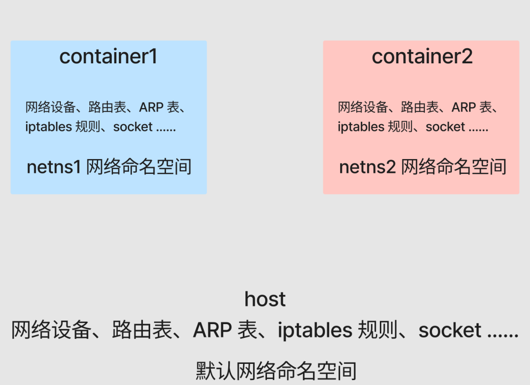
在 Linux 提供的多种 NameSpace 中,Network NameSpace 专门用于隔离网络视图。我们先看看宿主机默认所处的网络命名空间:
[root@host ~]# readlink /proc/$$/ns/net
net:[4026531956]
[root@host ~]#
以 net:[4026531956] 为例,net 代表命名空间类型,4026531956 则是其 inode 编号。
了解了容器的进程本质后,本文我们直接使用 Linux 底层能力来探索和还原容器网络的具体实现。接下来我们创建的进程,大家可以直接理解为独立的容器。
首先,使用 ip netns 工具创建两个网络命名空间 netns1 和 netns2:
[root@host ~]# ip netns add netns1
[root@host ~]# ip netns add netns2
[root@host ~]# ip netns list
netns2
netns1
[root@host ~]#
在这两个命名空间内分别启动一个 bash 进程(即容器),其中 container1 如下:
[root@host ~]# ip netns exec netns1 /bin/bash --rcfile <(echo "PS1=\"container1> \"")
container1> readlink /proc/$$/ns/net
net:[4026532165]
container1> ip link # 查看网络设备列表
1: lo: <LOOPBACK> mtu 65536 qdisc noop state DOWN mode DEFAULT group default qlen 1000
    link/loopback 00:00:00:00:00:00 brd 00:00:00:00:00:00
container1> route -n # 查看路由表
Kernel IP routing table
Destination     Gateway         Genmask         Flags Metric Ref    Use Iface
container1> iptables -L # 查看 iptables 规则
Chain INPUT (policy ACCEPT)
target     prot opt source               destination

Chain FORWARD (policy ACCEPT)
target     prot opt source               destination

Chain OUTPUT (policy ACCEPT)
target     prot opt source               destination
container1>
同样的,创建 container2:
[root@host ~]# ip netns exec netns2 /bin/bash --rcfile <(echo “PS2=\“container2> \”")
container2> readlink /proc/$$/ns/net
net:[4026532219]
container2> ip link # 查看网络设备列表
1: lo: <LOOPBACK> mtu 65536 qdisc noop state DOWN mode DEFAULT group default qlen 1000
    link/loopback 00:00:00:00:00:00 brd 00:00:00:00:00:00
container2> route -n # 查看路由表
Kernel IP routing table
Destination     Gateway         Genmask         Flags Metric Ref    Use Iface
container2> iptables -L # 查看 iptables 规则
Chain INPUT (policy ACCEPT)
target     prot opt source               destination

Chain FORWARD (policy ACCEPT)
target     prot opt source               destination

Chain OUTPUT (policy ACCEPT)
target     prot opt source               destination
container2>
可以看到,由于 Network NameSpace 的隔离作用,container1 和 container2 各自拥有独立的网络协议栈,包括网络设备、路由表、ARP 表、iptables 规则 等。每个容器都以为自己在独立的网络环境中运行。
现在,准备一个简单的 Go Web 服务,分别在 container1 和 container2 的后台运行:
package main

import (
 “fmt”
 “net/http”
 “os”
)

func main() {
 name := os.Args[1]
 http.HandleFunc(“/”, func(w http.ResponseWriter, r *http.Request) {
  fmt.Println(“req”)
  w.Write([]byte(name + “\n”))
 })
 fmt.Println(name, “listen :8080”)
 panic(http.ListenAndServe(“:8080”, nil))
}
在 container1 中启动:
container1> go run main.go container1 > container1.log &
[1] 2866
container1> tail container1.log
container1 listen :8080
container1>
在 container2 中启动:
container2> go run main.go container2 > container2.log &
[1] 2955
container2> tail container2.log
container2 listen :8080
container2>
现在,即便 container1 和 container2 都在同一个宿主机上监听 8080 端口,也不会发生冲突,因为它们处在不同的网络命名空间里。
测试一下服务的可用性(以 container1 为例):
container1> curl localhost:8080
curl: (7) Failed to connect to ::1: Network is unreachable
container1>
访问不通是因为我们还没有启用任何网络设备,包括基本的回环设备 lo。启用它即可:
container1> ifconfig
container1> ifup lo
container1> ifconfig
lo: flags=73<UP,LOOPBACK,RUNNING>  mtu 65536
        inet 127.0.0.1  netmask 255.0.0.0
        inet6 ::1  prefixlen 128  scopeid 0x10<host>
        loop  txqueuelen 1000  (Local Loopback)
        RX packets 0  bytes 0 (0.0 B)
        RX errors 0  dropped 0  overruns 0  frame 0
        TX packets 0  bytes 0 (0.0 B)
        TX errors 0  dropped 0 overruns 0  carrier 0  collisions 0

container1> curl localhost:8080
container1
container1>
container2 的操作与此相同。
容器点对点通信:Veth
目前,两个容器处于不同的 Network NameSpace 中,网络环境完全隔离,它们之间无法进行任何网络通信。
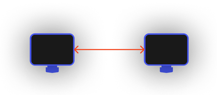
在思考解决方案前,让我们先回归现实世界:如果想让两台独立的计算机进行网络通信,我们该怎么做?
最简单的方法就是拿一根网线,将两台电脑的网口连接起来。

那么,在容器世界里,我们能否给每个容器也虚拟出一个可以“插网线”的网口呢?
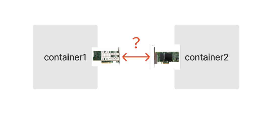
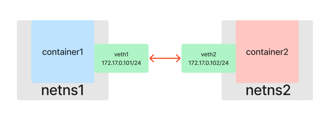
答案是肯定的。Linux 网络虚拟化技术提供了一种用软件模拟硬件网卡的方式:Veth(Virtual Ethernet devices,虚拟以太网设备)。
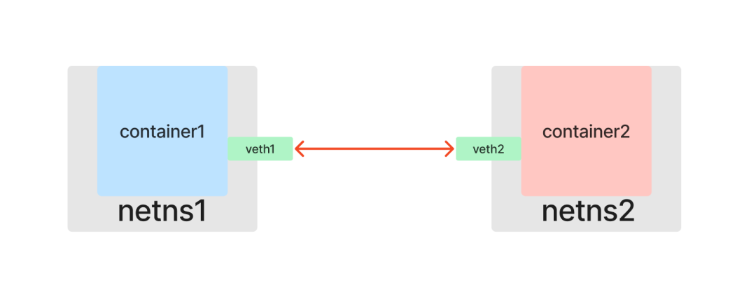
和一根网线有两端一样,Veth 也是成对出现的,因此被称为 veth pair。假设 veth1 和 veth2 是一对设备,那么从 veth1 进入的数据包会从 veth2 出来,反之亦然。只要将一对 Veth 分别放入两个 Network Namespace,这两个命名空间就能像通过网线直连一样互相通信。
现在开始动手实践。首先查看宿主机已有的网络设备:
[root@host ~]# ip link
1: lo: <LOOPBACK,UP,LOWER_UP> mtu 65536 qdisc noqueue state UNKNOWN mode DEFAULT group default qlen 1000
    link/loopback 00:00:00:00:00:00 brd 00:00:00:00:00:00
2: eth0: <BROADCAST,MULTICAST,UP,LOWER_UP> mtu 1500 qdisc mq state UP mode DEFAULT group default qlen 1000
    link/ether 52:54:00:26:eb:d4 brd ff:ff:ff:ff:ff:ff
[root@host ~]#
创建一个 veth pair,包含 veth1 和 veth2 两个虚拟设备:
[root@host ~]# ip link add veth1 type veth peer name veth2
[root@host ~]# ip link
1: lo: <LOOPBACK,UP,LOWER_UP> mtu 65536 qdisc noqueue state UNKNOWN mode DEFAULT group default qlen 1000
    link/loopback 00:00:00:00:00:00 brd 00:00:00:00:00:00
2: eth0: <BROADCAST,MULTICAST,UP,LOWER_UP> mtu 1500 qdisc mq state UP mode DEFAULT group default qlen 1000
    link/ether 52:54:00:26:eb:d4 brd ff:ff:ff:ff:ff:ff
3: veth2@veth1: <BROADCAST,MULTICAST,M-DOWN> mtu 1500 qdisc noop state DOWN mode DEFAULT group default qlen 1000
    link/ether 6a:01:c8:fa:9e:6e brd ff:ff:ff:ff:ff:ff
4: veth1@veth2: <BROADCAST,MULTICAST,M-DOWN> mtu 1500 qdisc noop state DOWN mode DEFAULT group default qlen 1000
    link/ether 42:7e:de:c6:89:ff brd ff:ff:ff:ff:ff:ff
[root@host ~]#
接下来,将一端的虚拟网卡 veth1 放入 netns1,另一端的 veth2 放入 netns2,这就相当于用“网线”连接了两个命名空间:
[root@host ~]# ip link set veth1 netns netns1
[root@host ~]# ip link set veth2 netns netns2
[root@host ~]#
连接完成后,我们就能在各自的容器里看到对应的网络设备了:
在 container1 中查看:
container1> ip link
1: lo: <LOOPBACK,UP,LOWER_UP> mtu 65536 qdisc noqueue state UNKNOWN mode DEFAULT group default qlen 1000
    link/loopback 00:00:00:00:00:00 brd 00:00:00:00:00:00
4: veth1@if3: <BROADCAST,MULTICAST> mtu 1500 qdisc noop state DOWN mode DEFAULT group default qlen 1000
    link/ether 42:7e:de:c6:89:ff brd ff:ff:ff:ff:ff:ff link-netnsid 1
container1>
在 container2 中查看:
container2> ip link
1: lo: <LOOPBACK,UP,LOWER_UP> mtu 65536 qdisc noqueue state UNKNOWN mode DEFAULT group default qlen 1000
    link/loopback 00:00:00:00:00:00 brd 00:00:00:00:00:00
3: veth2@if4: <BROADCAST,MULTICAST> mtu 1500 qdisc noop state DOWN mode DEFAULT group default qlen 1000
    link/ether 6a:01:c8:fa:9e:6e brd ff:ff:ff:ff:ff:ff link-netnsid 0
container2>
接下来,为这两个网卡分配 IP 地址,让它们位于同一个子网(例如 172.17.0.0/24)内,然后启用网卡。
在 container1 中配置:
container1> ip addr add 172.17.0.101/24 dev veth1
container1> ip link set dev veth1 up
container1> ifconfig
lo: flags=73<UP,LOOPBACK,RUNNING>  mtu 65536
        inet 127.0.0.1  netmask 255.0.0.0
        inet6 ::1  prefixlen 128  scopeid 0x10<host>
        loop  txqueuelen 1000  (Local Loopback)
        RX packets 10  bytes 942 (942.0 B)
        RX errors 0  dropped 0  overruns 0  frame 0
        TX packets 10  bytes 942 (942.0 B)
        TX errors 0  dropped 0 overruns 0  carrier 0  collisions 0

veth1: flags=4099<UP,BROADCAST,MULTICAST>  mtu 1500
        inet 172.17.0.101  netmask 255.255.255.0  broadcast 0.0.0.0
        ether 42:7e:de:c6:89:ff  txqueuelen 1000  (Ethernet)
        RX packets 0  bytes 0 (0.0 B)
        RX errors 0  dropped 0  overruns 0  frame 0
        TX packets 0  bytes 0 (0.0 B)
        TX errors 0  dropped 0 overruns 0  carrier 0  collisions 0

container1>
在 container2 中配置:
container2> ip addr add 172.17.0.102/24 dev veth2
container2> ip link set dev veth2 up
container2> ifconfig
lo: flags=73<UP,LOOPBACK,RUNNING>  mtu 65536
        inet 127.0.0.1  netmask 255.0.0.0
        inet6 ::1  prefixlen 128  scopeid 0x10<host>
        loop  txqueuelen 1000  (Local Loopback)
        RX packets 10  bytes 942 (942.0 B)
        RX errors 0  dropped 0  overruns 0  frame 0
        TX packets 10  bytes 942 (942.0 B)
        TX errors 0  dropped 0 overruns 0  carrier 0  collisions 0

veth2: flags=4163<UP,BROADCAST,RUNNING,MULTICAST>  mtu 1500
        inet 172.17.0.102  netmask 255.255.255.0  broadcast 0.0.0.0
        inet6 fe80::6801:c8ff:fefa:9e6e  prefixlen 64  scopeid 0x20<link>
        ether 6a:01:c8:fa:9e:6e  txqueuelen 1000  (Ethernet)
        RX packets 6  bytes 516 (516.0 B)
        RX errors 0  dropped 0  overruns 0  frame 0
        TX packets 6  bytes 516 (516.0 B)
        TX errors 0  dropped 0 overruns 0  carrier 0  collisions 0

container2>
配置完成后,测试容器间的服务互访:
从 container1 访问 container2:
container1> curl 172.17.0.102:8080
container2
container1>
从 container2 访问 container1:
container2> curl 172.17.0.101:8080
container1
container2>
至此,通过使用 Veth,我们成功构建了一个点对点的二层网络拓扑,解决了两个容器间的通信问题。
容器间互相通信:Bridge
现实世界的网络里不可能只有两台计算机。当有第三台、第四台甚至更多计算机需要接入网络时,我们不可能为每两台设备都单独拉一根网线。为了解决这个问题,工程师们发明了二层交换机(或网桥)。
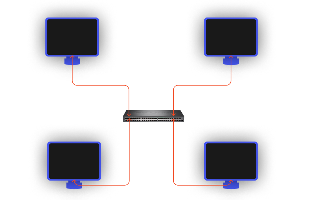
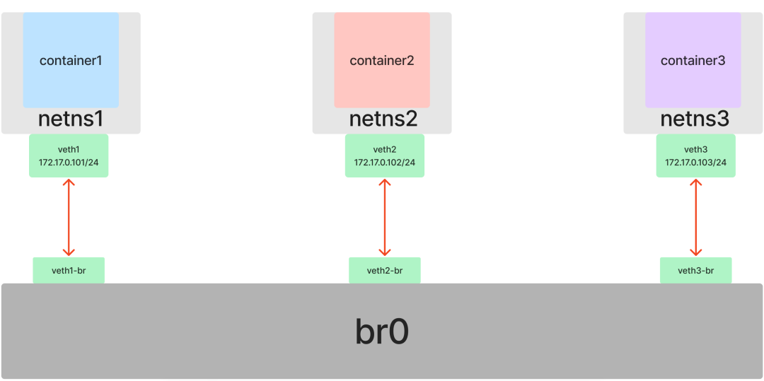
对于容器网络来说也是如此。如果我们有三个或更多的网络命名空间需要接入同一个二层网络,就不能再简单地仅使用 Veth 来两两直连了。幸运的是,Linux 不仅提供了虚拟网卡,也提供了虚拟交换机(网桥)的实现:Bridge。
在已有 netns1 和 netns2 的基础上,我们再创建一个 netns3:
[root@host ~]# ip netns add netns3
[root@host ~]# ip netns list
netns3
netns2 (id: 1)
netns1 (id: 0)
[root@host ~]#
重复之前的操作,创建并启动 container3:
[root@host ~]# ip netns exec netns3 /bin/bash --rcfile <(echo "PS1=\"container3> \"")
container3> readlink /proc/$$/ns/net
net:[4026532277]
container3> go run main.go container3 > container3.log &
[1] 4270
container3> tail container3.log
container3 listen :8080
container3> ifup lo
container3> ifconfig
lo: flags=73<UP,LOOPBACK,RUNNING>  mtu 65536
        inet 127.0.0.1  netmask 255.0.0.0
        inet6 ::1  prefixlen 128  scopeid 0x10<host>
        loop  txqueuelen 1000  (Local Loopback)
        RX packets 0  bytes 0 (0.0 B)
        RX errors 0  dropped 0  overruns 0  frame 0
        TX packets 0  bytes 0 (0.0 B)
        TX errors 0  dropped 0 overruns 0  carrier 0  collisions 0

container3> curl localhost:8080
container3
container3>
在为三个容器构建共享网络前,我们先把之前连接 container1 和 container2 的“网线”断开(只需在其中一端操作):
container1> ip link delete veth1
container1> ip link
1: lo: <LOOPBACK,UP,LOWER_UP> mtu 65536 qdisc noqueue state UNKNOWN mode DEFAULT group default qlen 1000
    link/loopback 00:00:00:00:00:00 brd 00:00:00:00:00:00
container1>
现在,三个容器又回到了互不相识的状态。
开始实践,首先创建一个 Bridge 并启用它:
[root@host ~]# ip link add br0 type bridge
[root@host ~]# ip link
1: lo: <LOOPBACK,UP,LOWER_UP> mtu 65536 qdisc noqueue state UNKNOWN mode DEFAULT group default qlen 1000
    link/loopback 00:00:00:00:00:00 brd 00:00:00:00:00:00
2: eth0: <BROADCAST,MULTICAST,UP,LOWER_UP> mtu 1500 qdisc mq state UP mode DEFAULT group default qlen 1000
    link/ether 52:54:00:26:eb:d4 brd ff:ff:ff:ff:ff:ff
5: br0: <BROADCAST,MULTICAST> mtu 1500 qdisc noop state DOWN mode DEFAULT group default qlen 1000
    link/ether 9e:ac:12:15:98:64 brd ff:ff:ff:ff:ff:ff
[root@host ~]# ip link set dev br0 up
[root@host ~]# ifconfig
br0: flags=4163<UP,BROADCAST,RUNNING,MULTICAST>  mtu 1500
        inet6 fe80::9cac:12ff:fe15:9864  prefixlen 64  scopeid 0x20<link>
        ether 9e:ac:12:15:98:64  txqueuelen 1000  (Ethernet)
        RX packets 0  bytes 0 (0.0 B)
        RX errors 0  dropped 0  overruns 0  frame 0
        TX packets 6  bytes 516 (516.0 B)
        TX errors 0  dropped 0 overruns 0  carrier 0  collisions 0

eth0: flags=4163<UP,BROADCAST,RUNNING,MULTICAST>  mtu 1500
        inet 10.0.12.15  netmask 255.255.252.0  broadcast 10.0.15.255
        inet6 fe80::5054:ff:fe26:ebd4  prefixlen 64  scopeid 0x20<link>
        ether 52:54:00:26:eb:d4  txqueuelen 1000  (Ethernet)
        RX packets 114601  bytes 160971385 (153.5 MiB)
        RX errors 0  dropped 0  overruns 0  frame 0
        TX packets 18824  bytes 2035143 (1.9 MiB)
        TX errors 0  dropped 0 overruns 0  carrier 0  collisions 0

lo: flags=73<UP,LOOPBACK,RUNNING>  mtu 65536
        inet 127.0.0.1  netmask 255.0.0.0
        inet6 ::1  prefixlen 128  scopeid 0x10<host>
        loop  txqueuelen 1000  (Local Loopback)
        RX packets 15  bytes 2000 (1.9 KiB)
        RX errors 0  dropped 0  overruns 0  frame 0
        TX packets 15  bytes 2000 (1.9 KiB)
        TX errors 0  dropped 0 overruns 0  carrier 0  collisions 0

[root@host ~]#
现在准备三条“网线”(三对 veth):
[root@host ~]# ip link add veth1 type veth peer name veth1-br
[root@host ~]# ip link add veth2 type veth peer name veth2-br
[root@host ~]# ip link add veth3 type veth peer name veth3-br
[root@host ~]#
接下来,将每对 veth 的一端放入对应的容器命名空间,另一端“插到”网桥 br0 上并启用:
[root@host ~]# ip link set dev veth1 netns netns1
[root@host ~]# ip link set dev veth2 netns netns2
[root@host ~]# ip link set dev veth3 netns netns3
[root@host ~]# ip link set dev veth1-br master br0
[root@host ~]# ip link set dev veth2-br master br0
[root@host ~]# ip link set dev veth3-br master br0
[root@host ~]# ip link set dev veth1-br up
[root@host ~]# ip link set dev veth2-br up
[root@host ~]# ip link set dev veth3-br up
[root@host ~]#
然后,在每个容器中为各自的 veth 网卡配置 IP 地址(位于同一子网 172.17.0.0/24 内)并启用:
在 container1 中:
container1> ip addr add 172.17.0.101/24 dev veth1
container1> ip link set dev veth1 up
container1>
在 container2 中:
container2> ip addr add 172.17.0.102/24 dev veth2
container2> ip link set dev veth2 up
container2>
在 container3 中:
container3> ip addr add 172.17.0.103/24 dev veth3
container3> ip link set dev veth3 up
container3>
配置完成后,测试三个容器间的服务互访:
测试 container1:
container1> curl 172.17.0.102:8080
container2
container1> curl 172.17.0.103:8080
container3
container1>
测试 container2:
container2> curl 172.17.0.101:8080
container1
container2> curl 172.17.0.103:8080
container3
container2>
测试 container3:
container3> curl 172.17.0.101:8080
container1
container3> curl 172.17.0.102:8080
container2
container3>
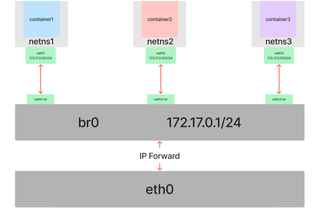
至此,我们在 Veth 的基础上引入了 Bridge,成功地将多个命名空间连接到了同一个二层网络中,解决了多个容器间互相通信的问题。
容器与外部网络通信:route 和 iptables
到目前为止,我们的实验都局限在同一个子网内。但实际应用场景中,容器往往需要与外部网络进行通信。
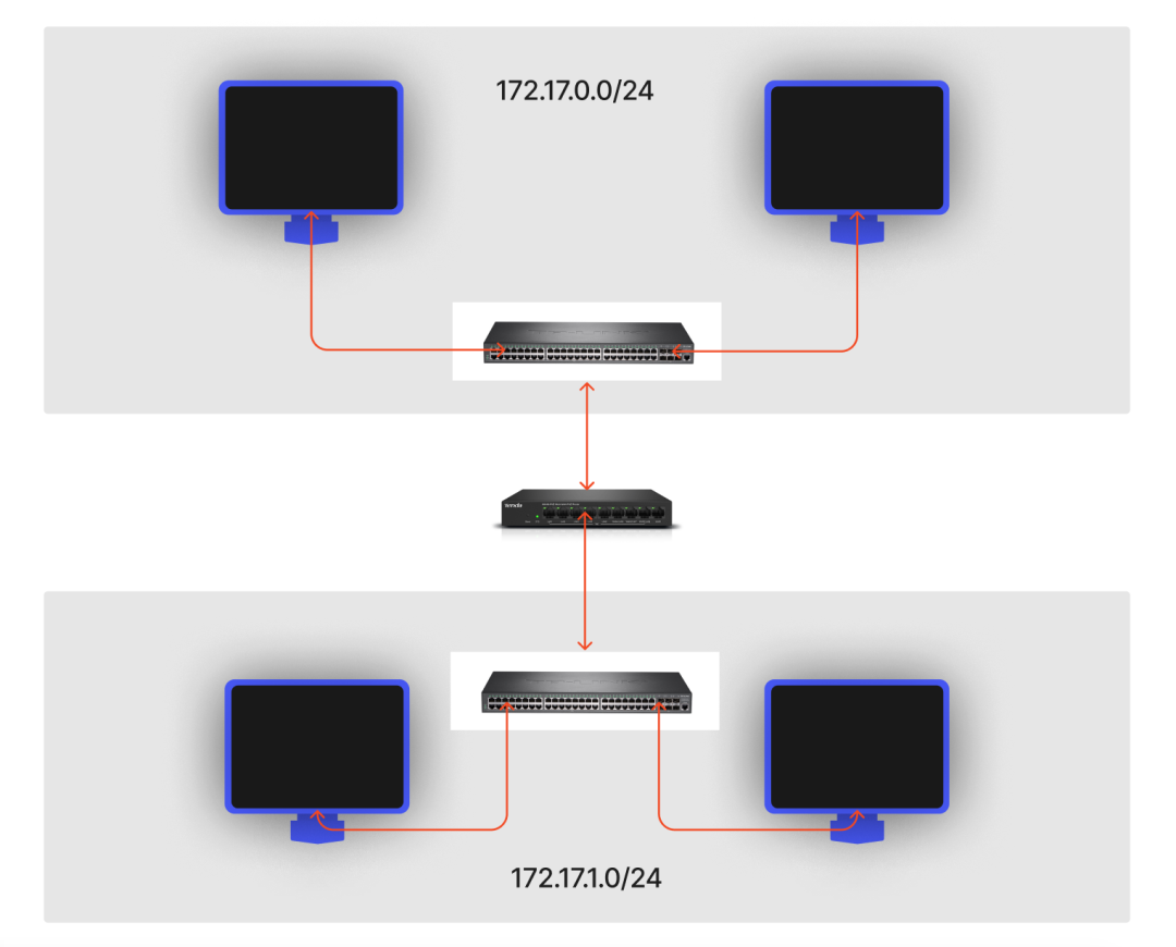
在现实网络中,二层交换机只能解决同一子网内的通信,不同子网间的数据转发则需要三层路由器(或网关)来完成。
与虚拟交换机不同,Linux 本身并没有提供一个独立的“虚拟路由器”设备。这是因为 Linux 内核自身就具备了强大的路由功能,完全可以充当路由器。更准确地说,在 Linux 中,一个 Network Namespace 就可以承担一个路由器的角色。
在 Linux Network Namespace 中,路由功能的核心在于路由表。通过定义路由表规则,就能决定数据包的流向。常用的路由表有 local 和 main,local 表的优先级高于 main。例如,访问本机(localhost)的请求会直接在 local 表中匹配规则,而不会进入 main 表。
查看系统所有的路由表定义:
[root@host ~]# cat /etc/iproute2/rt_tables
#
# reserved values
#
255     local
254     main
253     default
0       unspec
#
# local
#
#1      inr.ruhep
[root@host ~]#
查看指定路由表的规则,可以使用 ip route list table <表名>:
[root@host ~]# ip route list table local
broadcast 10.0.12.0 dev eth0 proto kernel scope link src 10.0.12.15
local 10.0.12.15 dev eth0 proto kernel scope host src 10.0.12.15
broadcast 10.0.15.255 dev eth0 proto kernel scope link src 10.0.12.15
broadcast 127.0.0.0 dev lo proto kernel scope link src 127.0.0.1
local 127.0.0.0/8 dev lo proto kernel scope host src 127.0.0.1
local 127.0.0.1 dev lo proto kernel scope host src 127.0.0.1
broadcast 127.255.255.255 dev lo proto kernel scope link src 127.0.0.1
[root@host ~]# ip route list table main
default via 10.0.12.1 dev eth0
10.0.12.0/22 dev eth0 proto kernel scope link src 10.0.12.15
169.254.0.0/16 dev eth0 scope link metric 1002
[root@host ~]# route -n
Kernel IP routing table
Destination     Gateway         Genmask         Flags Metric Ref    Use Iface
0.0.0.0         10.0.12.1       0.0.0.0         UG    0      0        0 eth0
10.0.12.0       0.0.0.0         255.255.252.0   U     0      0        0 eth0
169.254.0.0     0.0.0.0         255.255.0.0     U     1002   0        0 eth0
[root@host ~]#
我们常用的 route -n 命令查看的正是 main 路由表。
容器和宿主机互通
我们现有的三个容器(container1, container2, container3)IP 分别为 172.17.0.101、172.17.0.102、172.17.0.103,它们同属一个子网。
先查看宿主机的 IP 地址,这里是 10.0.12.15:
[root@host ~]# ifconfig
...
eth0: flags=4163<UP,BROADCAST,RUNNING,MULTICAST>  mtu 1500
        inet 10.0.12.15  netmask 255.255.252.0  broadcast 10.0.15.255
        inet6 fe80::5054:ff:fe26:ebd4  prefixlen 64  scopeid 0x20<link>
        ether 52:54:00:26:eb:d4  txqueuelen 1000  (Ethernet)
        RX packets 119923  bytes 161411733 (153.9 MiB)
        RX errors 0  dropped 0  overruns 0  frame 0
        TX packets 24106  bytes 2884317 (2.7 MiB)
        TX errors 0  dropped 0 overruns 0  carrier 0  collisions 0
...
[root@host ~]#
再看一下容器(以 container1 为例)的路由规则:
container1> route -n
Kernel IP routing table
Destination     Gateway         Genmask         Flags Metric Ref    Use Iface
172.17.0.0      0.0.0.0         255.255.255.0   U     0      0        0 veth1
container1>
目前容器的路由表只有一条规则:访问 172.17.0.0/24 子网内的 IP(如 172.17.0.102)时,数据包直接发往 veth1 设备。通过 Veth 和 Bridge 的联动,最终能到达目标容器。
为了让容器能访问宿主机(IP 10.0.12.15),我们需要增加一条路由规则。从宿主机角度看,br0 网桥也是一张存在于默认网络命名空间中的网卡。我们可以为它配置一个 IP,让它充当容器的网关(三层路由器)。
为宿主机上的 br0 设备设置 IP 地址 172.17.0.1(与容器在同一子网):
[root@host ~]# ip addr add local 172.17.0.1/24 dev br0
[root@host ~]# ifconfig
br0: flags=4163<UP,BROADCAST,RUNNING,MULTICAST>  mtu 1500
        inet 172.17.0.1  netmask 255.255.255.0  broadcast 0.0.0.0
        inet6 fe80::9cac:12ff:fe15:9864  prefixlen 64  scopeid 0x20<link>
        ether 16:bd:7d:ca:53:bf  txqueuelen 1000  (Ethernet)
        RX packets 27  bytes 1716 (1.6 KiB)
        RX errors 0  dropped 0  overruns 0  frame 0
        TX packets 8  bytes 656 (656.0 B)
        TX errors 0  dropped 0 overruns 0  carrier 0  collisions 0
......
设置后,宿主机自动增加了一条指向 br0 的路由规则:
[root@host ~]# route -n
Kernel IP routing table
Destination     Gateway         Genmask         Flags Metric Ref    Use Iface
0.0.0.0         10.0.12.1       0.0.0.0         UG    0      0        0 eth0
10.0.12.0       0.0.0.0         255.255.252.0   U     0      0        0 eth0
169.254.0.0     0.0.0.0         255.255.0.0     U     1002   0        0 eth0
172.17.0.0      0.0.0.0         255.255.255.0   U     0      0        0 br0
[root@host ~]#
根据这条规则,宿主机现在可以直接访问容器了:
[root@host ~]# ping 172.17.0.101
PING 172.17.0.101 (172.17.0.101) 56(84) bytes of data.
64 bytes from 172.17.0.101: icmp_seq=1 ttl=64 time=0.025 ms
64 bytes from 172.17.0.101: icmp_seq=2 ttl=64 time=0.037 ms
64 bytes from 172.17.0.101: icmp_seq=3 ttl=64 time=0.031 ms
^C
--- 172.17.0.101 ping statistics ---
3 packets transmitted, 3 received, 0% packet loss, time 1999ms
rtt min/avg/max/mdev = 0.025/0.031/0.037/0.005 ms
[root@host ~]# curl 172.17.0.101:8080
container1
[root@host ~]#
接下来解决容器访问宿主机的问题。我们需要为容器添加一条默认路由,指定网关为 172.17.0.1(即 br0 的 IP):
container1> ip route add default via 172.17.0.1
container1> route -n
Kernel IP routing table
Destination     Gateway         Genmask         Flags Metric Ref    Use Iface
0.0.0.0         172.17.0.1      0.0.0.0         UG    0      0        0 veth1
172.17.0.0      0.0.0.0         255.255.255.0   U     0      0        0 veth1
container1>
现在,当容器访问宿主机 IP 时,数据包会发往网关 172.17.0.1,进而到达宿主机的 br0 网卡。宿主机发现这个 IP 数据包的目的地是自己,就会进行处理。测试一下:
container1> ping 10.0.12.15
PING 10.0.12.15 (10.0.12.15) 56(84) bytes of data.
64 bytes from 10.0.12.15: icmp_seq=1 ttl=64 time=0.022 ms
64 bytes from 10.0.12.15: icmp_seq=2 ttl=64 time=0.031 ms
64 bytes from 10.0.12.15: icmp_seq=3 ttl=64 time=0.032 ms
^C
--- 10.0.12.15 ping statistics ---
3 packets transmitted, 3 received, 0% packet loss, time 1999ms
rtt min/avg/max/mdev = 0.022/0.028/0.032/0.006 ms
container1>
容器访问其它主机(外网)
上面我们配置了容器访问宿主机的路由,但 Linux 默认会丢弃那些目的 IP 不属于本机的数据包。假设同一子网内还有另一台主机 host2,IP 为 10.0.12.11。在容器内尝试 ping 它或访问外网,都会失败:
container1> ping 10.0.12.11
PING 10.0.12.11 (10.0.12.11) 56(84) bytes of data.
^C
--- 10.0.12.11 ping statistics ---
16 packets transmitted, 0 received, 100% packet loss, time 14999ms

container1> curl baidu.com
curl: (6) Could not resolve host: baidu.com; Unknown error
container1>
为了让容器能访问外部网络,我们需要开启 Linux 的 IP 转发功能,让它不要丢弃目的 IP 非本机的数据包,而是继续将其转发出去:
[root@host ~]# cat /proc/sys/net/ipv4/ip_forward # 0 代表关闭,1 代表开启
0
[root@host ~]# vi /etc/sysctl.d/30-ipforward.conf
net.ipv4.ip_forward=1
net.ipv6.conf.default.forwarding=1
net.ipv6.conf.all.forwarding=1
[root@host ~]# sysctl -p /etc/sysctl.d/30-ipforward.conf
net.ipv4.ip_forward = 1
net.ipv6.conf.default.forwarding = 1
net.ipv6.conf.all.forwarding = 1
[root@host ~]# cat /proc/sys/net/ipv4/ip_forward # 0 代表关闭,1 代表开启
1
[root@host ~]#
但这还不够。当容器访问外网时,Linux 确实能帮我们把请求转发出去(br0 -> eth0),但外部主机在收到响应请求时,却不认识我们内部使用的 172.17.0.0/24 这个网段,因此无法正确回包。这就需要用到 NAT(网络地址转换) 技术。
在这里,我们需要修改的是数据包的源 IP 地址,即 SNAT(源地址转换),将容器发出的数据包的源 IP 转换成宿主机出口网卡(eth0)的 IP。在 Linux 中,我们可以通过 iptables 的 MASQUERADE 策略来实现:
[root@host ~]# iptables -t nat -A POSTROUTING -s 172.17.0.0/24 ! -o br0 -j MASQUERADE
[root@host ~]# iptables -t nat -nL
Chain PREROUTING (policy ACCEPT)
target     prot opt source               destination

Chain INPUT (policy ACCEPT)
target     prot opt source               destination

Chain OUTPUT (policy ACCEPT)
target     prot opt source               destination

Chain POSTROUTING (policy ACCEPT)
target     prot opt source               destination
MASQUERADE  all  --  172.17.0.0/24        0.0.0.0/0
[root@host ~]#
这条规则的意思是:对所有源地址为 172.17.0.0/24 且不是从 br0 网卡发出的数据包(即从容器发出、即将经由宿主机的其他网卡如 eth0 出去的包)进行 MASQUERADE(SNAT)处理。
现在,容器就可以访问外部网络了:
container1> ping 10.0.12.11
PING 10.0.12.11 (10.0.12.11) 56(84) bytes of data.
64 bytes from 10.0.12.11: icmp_seq=1 ttl=63 time=0.231 ms
64 bytes from 10.0.12.11: icmp_seq=2 ttl=63 time=0.216 ms
64 bytes from 10.0.12.11: icmp_seq=3 ttl=63 time=0.206 ms
^C
--- 10.0.12.11 ping statistics ---
3 packets transmitted, 3 received, 0% packet loss, time 1999ms
rtt min/avg/max/mdev = 0.206/0.217/0.231/0.019 ms
container1> curl baidu.com
<html>
<meta http-equiv="refresh" content="0;url=http://www.baidu.com/">
</html>
container1>
外部访问容器(容器端口映射)
容器与外部网络通信,我们已经解决了容器访问宿主机、容器访问外网的问题,最后剩下:如何让外部网络主动访问容器内的服务?
在 Docker 中,我们通过端口映射来实现,例如:
[root@host ~]# docker run -p 8000:8080 xxx
-p 参数将容器内的 8080 端口映射到宿主机的 8000 端口。这样外部客户端通过访问 宿主机IP:8000 就能访问到容器服务。
这一技术同样基于 NAT,但这次需要修改的是数据包的目的 IP 地址和端口,即 DNAT(目的地址转换)。我们可以通过 iptables 的 DNAT 策略来实现:
[root@host ~]# iptables -t nat -A PREROUTING  ! -i br0 -p tcp -m tcp --dport 8000 -j DNAT --to-destination 172.17.0.101:8080
[root@host ~]# iptables -t nat -nL
Chain PREROUTING (policy ACCEPT)
target     prot opt source               destination
DNAT       tcp  --  0.0.0.0/0            0.0.0.0/0            tcp dpt:8000 to:172.17.0.101:8080

Chain INPUT (policy ACCEPT)
target     prot opt source               destination

Chain OUTPUT (policy ACCEPT)
target     prot opt source               destination

Chain POSTROUTING (policy ACCEPT)
target     prot opt source               destination
MASQUERADE  all  --  172.17.0.0/24        0.0.0.0/0
[root@host ~]#
这条规则的意思是:将所有访问宿主机 8000 端口的 TCP 请求(且不是从 br0 网卡进来的,即来自外部的请求),转发到 172.17.0.101(container1)的 8080 端口。
现在,外部主机 host2(IP 10.0.12.11)就可以通过访问 10.0.12.15:8000 来访问 container1 的服务了:
[root@host2 ~]# curl 10.0.12.15:8000
container1
[root@host2 ~]#
至此,我们已经完整实现了一个与 Docker 默认网络模式(Bridge)几乎一致的网络拓扑结构。
总结
Docker 容器网络的核心技术正是我们上面实践的内容:Veth + Bridge + route + iptables。Docker 所做的,本质上是用 Go 语言将这些底层的 Linux 网络配置自动化、封装化。
只有深入理解了这些底层原理,当我们在日常工作中遇到复杂的容器网络问题时,才能做到心中有数,从容应对。
本文探讨的只是 Docker 自身的默认网络模型。在更广阔的 云原生 领域,例如 Kubernetes 所使用的 CNI(容器网络接口)模型,以及 Service Mesh 与 CNI 结合的层次化 SDN(软件定义网络)方案,其网络架构将会更加复杂和强大。
如果你对这类深入底层的技术原理和实践感兴趣,欢迎到 云栈社区 与我们继续交流探讨,共同学习成长。
 发表于 2026-4-8 03:15:54
|
查看: 124|
回复: 0
发表于 2026-4-8 03:15:54
|
查看: 124|
回复: 0
