本次实验的目标是把 I²C 相关的功能搞定,尝试驱动 SSD1306 0.96 寸 OLED 屏幕以及 BME280 传感器,最终将传感器读到的数据和实时时间显示在屏幕上。
硬件部分
1. I²C协议简介
I²C通讯协议(Inter-Integrated Circuit)由于它引脚少,硬件实现简单,可扩展性强,现在被广泛地使用在系统内多个集成电路(IC)间的通讯。
在计算机科学里,大部分复杂的问题都可以通过分层来简化。如芯片被分为内核层和片上外设;瑞萨的 FSP 库则是在寄存器与用户代码之间的软件层。
对于通讯协议,我们也以分层的方式来理解,最基本的是把它分为物理层和协议层。物理层规定通讯系统中具有机械、电子功能部分的特性,确保原始数据在物理媒体的传输。协议层主要规定通讯逻辑,统一收发双方的数据打包、解包标准。简单来说物理层规定我们用嘴巴还是用肢体来交流,协议层则规定我们用中文还是英文来交流。
(具体的 I²C 协议入门可以复制下方链接到浏览器查看)
A Basic Guideto I²C - Texas Instruments
https://www.ti.com/lit/an/sbaa565/sbaa565.pdf
2. OLED屏幕
本次使用的屏幕是 0.96 寸 4 针 I²C 协议 OLED 屏幕,其驱动 IC 为 SSD1306,屏幕分辨率为 128x64。
编程时参考的数据手册,具体的修改参考软件部分。
(相关信息可以复制下方链接到浏览器查看)
数据手册
https://cdn-shop.adafruit.com/datasheets/SSD1306.pdf
3. BME280温湿度气压传感器
BME280 是一款由 Bosch Sensortec 开发的多功能环境传感器,可同时精确测量温度、湿度和气压,具有低功耗和小尺寸的特点,广泛应用于气象监测、室内导航、健康监测及物联网等领域。
软件部分
将先前 03_RTC 工程复制一份,重命名为 04_OLED_BME280-I2C。
1. 配置 I²C
首先在 e² studio 内配置 I²C。
| 序号 |
操作 |
| 1 |
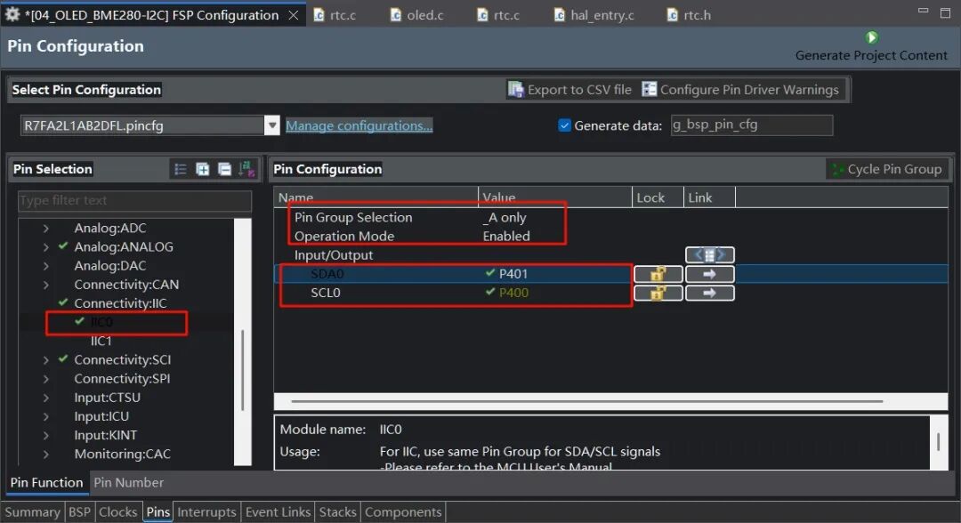
点击界面下方标签栏中的 Pins 标签,进入引脚配置界面。 |
| 2 |
在 Pin Selection 区域,展开 Connectivity: I²C 选项,选择 I²C0。 |
| 3 |
在 Pin Configuration 区域,将 Pin Group Selection 设置为 _A only,Operation Mode 设置为 Enabled。 |
| 4 |
勾选 SDA0 对应的 P401 引脚和 SCL0 对应的 P400 引脚。 |
| 序号 |
操作 |
| 1 |
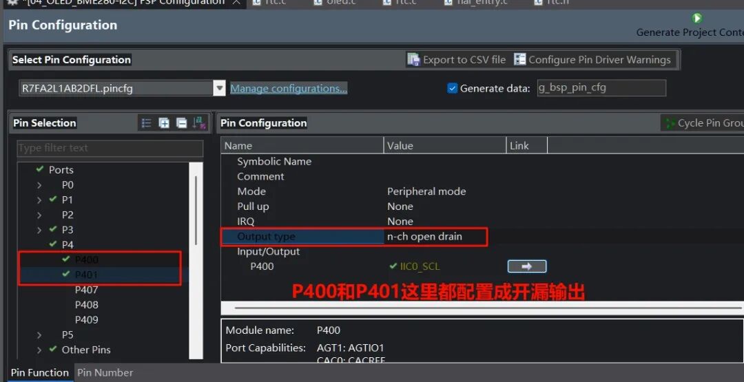
在 Pin Selection 区域,分别选择 P400 和 P401 引脚。 |
| 2 |
将 Output type 设置为 n-ch open drain,把 P400 和 P401 配置成开漏输出。 |
| 序号 |
操作 |
| 1 |
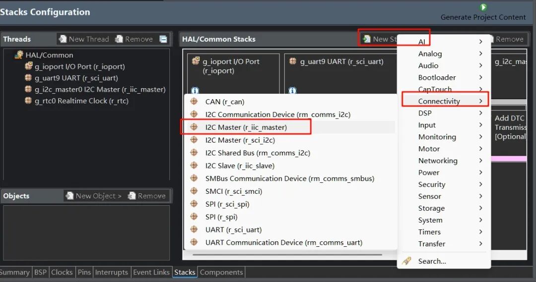
点击界面下方标签栏中的 Stacks 标签,进入堆栈配置页面。 |
| 2 |
在 HAL/Common Stacks 区域,点击 New Stack 按钮。 |
| 3 |
在弹出菜单中,选择 Connectivity 选项。 |
| 4 |
在 Connectivity 子菜单中,选择 I2C Master (r_iic_master)。 |
| 序号 |
操作 |
| 1 |
在 HAL/Common Stacks 区域,点击选中 g_i2c_master0 I2C Master (r_iic_master)。 |
| 2 |
在下方 Settings 设置区域的 Module g_i2c_master0 I2C Master (r_iic_master) 部分,将 Rate 设置为 Fast-mode。 |
| 3 |
Module g_i2c_master0 I2C Master (r_iic_master) 部分,设置 Slave Address 为 0x3c。 |
| 4 |
Module g_i2c_master0 I2C Master (r_iic_master) 部分,设置 Callback 为 iic_callback,Interrupt Priority Level 为 Priority 2。 |
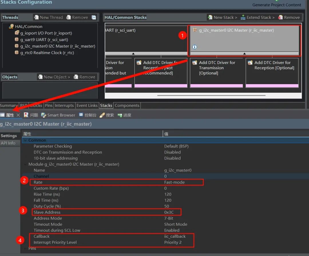
这里说明一下,在移植 OLED 驱动库时看到屏幕地址为 0x78,即 01111000,是包含读写位的(最低位)。而瑞萨这里是 7 位地址,不含读写位,因此要将 0x78 右移 1 位,即 0x3C(0111100)。
确认上面设置没问题后,生成项目代码。
2. 编写代码
I²C通信相关
新建 i2c.c 和 i2c.h 文件。
i2c.h
#ifndef I2C_H_
#define I2C_H_

extern volatile bool i2c_rx_complete;
extern volatile bool i2c_tx_complete;

void i2c_wait_rx();
void i2c_wait_tx();
#endif
i2c.c
#include "hal_data.h"
#include "i2c.h"

volatile bool i2c_rx_complete = false;
volatile bool i2c_tx_complete = false;
uint16_t timeout = 0;

void iic_callback(i2c_master_callback_args_t *p_args)
{
    if (p_args->event == I2C_MASTER_EVENT_RX_COMPLETE)
    {
        i2c_rx_complete = true;
    }
    else if (p_args->event == I2C_MASTER_EVENT_TX_COMPLETE)
    {
        i2c_tx_complete = true;
    }
}

void i2c_wait_tx()
{
    timeout = 1000;
    while (!i2c_tx_complete && timeout > 0)
    {
        timeout--;
    }
    i2c_tx_complete = false;
}

void i2c_wait_rx()
{
    timeout = 1000;
    while (!i2c_rx_complete && timeout > 0)
    {
        timeout--;
    }
    i2c_rx_complete = false;
}
由于瑞萨FSP库的高集成度,我只需要编写代码实现回调函数 iic_callback、等待发送函数 i2c_wait_tx、等待接收 i2c_wait_rx 函数改变标志位即可。
BME280操作相关
bme280.h
#ifndef BME280_H_
#define BME280_H_
#include "hal_data.h"
#define BME280_ID 0x60
typedef struct
{
    double humi, temp, press;
    bool initialized;
} BME_Struct;

void BME280_Get_Data(BME_Struct *bme);
void BME280_Init(BME_Struct *bme);
void BME280_Write_then_Read(uint8_t *src, uint8_t write_bytes, uint8_t *data_dest, uint8_t read_bytes);
void BME280_Trimming_Values();
double BME280_compensate_T_double(int32_t adc_T);
double BME280_compensate_P_double(int32_t adc_P);
double bme280_compensate_H_double(int32_t adc_H);

#endif /* BME280_H_ */
bme280.c(主要函数摘要)
#include "bme280.h"
#include "hal_data.h"
#include "i2c.h"

uint16_t dig_T1;
int16_t dig_T2;
int16_t dig_T3;
uint16_t dig_P1;
int16_t dig_P2;
int16_t dig_P3;
int16_t dig_P4;
int16_t dig_P5;
int16_t dig_P6;
int16_t dig_P7;
int16_t dig_P8;
int16_t dig_P9;

int8_t dig_H1;
int16_t dig_H2;
int8_t dig_H3;
int16_t dig_H4;
int16_t dig_H5;
int8_t dig_H6;

void BME280_Write_then_Read(uint8_t *src, uint8_t write_bytes, uint8_t *data_dest, uint8_t read_bytes)
{
    //临时设置I2C从机地址为0x76
    g_i2c_master0.p_api->slaveAddressSet(&g_i2c_master0_ctrl, 0x76, I2C_MASTER_ADDR_MODE_7BIT);
    g_i2c_master0.p_api->write(&g_i2c_master0_ctrl, src, write_bytes, true);
    i2c_wait_tx();
    g_i2c_master0.p_api->read(&g_i2c_master0_ctrl, data_dest, read_bytes, false);
    i2c_wait_rx();
    g_i2c_master0.p_api->slaveAddressSet(&g_i2c_master0_ctrl, 0x3C, I2C_MASTER_ADDR_MODE_7BIT);
}

void BME280_Init(BME_Struct *bme)
{
    uint8_t reg = 0xD0;
    uint8_t write_settings[7] = {0x00};
    uint8_t read_data;
    BME280_Write_then_Read(®, 1, &read_data, 1);
    if (read_data != BME280_ID)
    {
        printf("Init BME280 Failed!\n");
        bme->initialized = false;
        return;
    }
    else
    {
        bme->initialized = true;
    }

    write_settings[0] = 0xF2; // 设置湿度采集的寄存器 0xF2
    write_settings[1] = 0x05; // 00000 101 湿度 oversampling x16
    write_settings[2] = 0xF4; // 设置温度采集、气压采集、工作模式的寄存器 0xF4
    write_settings[3] = 0x93; // 100 100 11 温度和气压 oversampling x8,模式为normal
    write_settings[4] = 0xF5; // 配置config寄存器
    write_settings[5] = 0x10; // 000 100 0 0 ,配置滤波器系数为16
    g_i2c_master0.p_api->slaveAddressSet(&g_i2c_master0_ctrl, 0x76, I2C_MASTER_ADDR_MODE_7BIT);
    g_i2c_master0.p_api->write(&g_i2c_master0_ctrl, &write_settings[0], 6, false);
    i2c_wait_tx();
    g_i2c_master0.p_api->slaveAddressSet(&g_i2c_master0_ctrl, 0x3C, I2C_MASTER_ADDR_MODE_7BIT);
    R_BSP_SoftwareDelay(2, BSP_DELAY_UNITS_MILLISECONDS);
    // 校准数据
    BME280_Trimming_Values();
}

//... BME280_Trimming_Values, BME280_compensate_T_double, BME280_compensate_P_double, bme280_compensate_H_double 等函数(具体代码基于官方数据手册,此处从略)
void BME280_Get_Data(BME_Struct *bme)
{
    uint8_t dat[8] = {0};
    uint32_t press_t, temp_t, hum_t = 0;
    uint8_t reg = 0xF7;

    BME280_Write_then_Read(®, 1, &dat[0], 8);
    R_BSP_SoftwareDelay(2, BSP_DELAY_UNITS_MILLISECONDS);
    press_t = ((((uint32_t)dat[0] << 12) | ((uint32_t)dat[1] << 4)) | ((uint32_t)dat[2] >> 4));
    temp_t = ((((uint32_t)dat[3] << 12) | ((uint32_t)dat[4] << 4)) | ((uint32_t)dat[5] >> 4));
    hum_t = (((uint32_t)dat[6] << 8) | (uint32_t)dat[7]);

    bme->temp = BME280_compensate_T_double(temp_t);
    bme->press = BME280_compensate_P_double(press_t) / 100.0;
    bme->humi = bme280_compensate_H_double(hum_t);
}
BME280_compensate_T_doublebme280_compensate_H_doubleBME280_compensate_P_double
这三个函数分别为温度、湿度、气压的补偿算法函数,借鉴了 BME280 官方数据手册内给出的参考代码。
bme280 工作流程为
| 步骤 |
内容 |
| 1 |
上电初始化 |
| 2 |
写入 0xF2、0xF4、0xF5 寄存器以设定过采样率等参数 |
| 3 |
获取校准数据 |
| 4 |
调用 BME280_Get_Data 函数,读取 0xF7~0xFE 寄存器的数据 |
| 5 |
调用补偿算法函数得到人类可读的数值 |
注意
在写入+读取函数后记得跟1~5ms的延时,再进行下一步操作,否则会因为 bme280 侧的数据未准备好,有极大概率读取到错误数据或读不到数据。
OLED屏幕操作相关
oled.h
#ifndef OLED_H_
#define OLED_H_

#include "hal_data.h"

#define OLED_CMD 0  // 写命令
#define OLED_DATA 1 // 写数据
void OLED_ClearPoint(uint8_t x, uint8_t y);
void OLED_ColorTurn(uint8_t i);
void OLED_DisplayTurn(uint8_t i);
void OLED_WR_Byte(uint8_t dat, uint8_t mode);
void OLED_DisPlay_On(void);
void OLED_DisPlay_Off(void);
void OLED_Refresh(void);
void OLED_Clear(void);
void OLED_DrawPoint(uint8_t x, uint8_t y, uint8_t t);
void OLED_DrawLine(uint8_t x1, uint8_t y1, uint8_t x2, uint8_t y2, uint8_t mode);
void OLED_DrawCircle(uint8_t x, uint8_t y, uint8_t r);
void OLED_ShowChar(uint8_t x, uint8_t y, uint8_t chr, uint8_t size1);
void OLED_ShowString(uint8_t x, uint8_t y, uint8_t *chr, uint8_t size1);
void OLED_ShowNum(uint8_t x, uint8_t y, uint32_t num, uint8_t len, uint8_t size1);
void OLED_ShowChinese(uint8_t x, uint8_t y, uint8_t num, uint8_t size1);
void OLED_ScrollDisplay(uint8_t num, uint8_t space);
void OLED_ShowPicture(uint8_t x, uint8_t y, uint8_t sizex, uint8_t sizey, uint8_t BMP[], uint8_t mode);
void OLED_Init(void);

#endif
oled.c(核心函数摘要)
#include "oled.h"
#include "oled_font.h"
#include "i2c.h"

volatile uint8_t OLED_GRAM[144][8];
// 发送一个字节
// mode:数据/命令标志 0,表示命令;1,表示数据;
void OLED_WR_Byte(uint8_t dat, uint8_t mode)
{
    uint8_t data[2];
    if (mode)
    {
        data[0] = 0x40;
    }
    else
    {
        data[0] = 0x00;
    }
    data[1] = dat;
    R_IIC_MASTER_Write(&g_i2c_master0_ctrl, data, 2, false);
    i2c_wait_tx();
}
// 更新显存到OLED
void OLED_Refresh(void)
{
    uint8_t i, n;
    for (i = 0; i < 8; i++)
    {
        OLED_WR_Byte(0xb0 + i, OLED_CMD); // 设置行起始地址
        OLED_WR_Byte(0x00, OLED_CMD);     // 设置低列起始地址
        OLED_WR_Byte(0x10, OLED_CMD);     // 设置高列起始地址
        for (n = 0; n < 128; n++)
        {
            OLED_WR_Byte(OLED_GRAM[n][i], OLED_DATA);
        }
    }
}
// OLED的初始化
void OLED_Init(void)
{
    OLED_WR_Byte(0xAE, OLED_CMD); //--turn off oled panel 关闭显示
    OLED_WR_Byte(0x00, OLED_CMD); //---set low column address
    OLED_WR_Byte(0x10, OLED_CMD); //---set high column address
    OLED_WR_Byte(0x40, OLED_CMD); //--set start line address  Set Mapping RAM Display Start Line (0x00~0x3F)
    OLED_WR_Byte(0x81, OLED_CMD); //--set contrast control register
    OLED_WR_Byte(0xCF, OLED_CMD); // Set SEG Output Current Brightness
    OLED_WR_Byte(0xA1, OLED_CMD); //--Set SEG/Column Mapping     0xa0左右反置 0xa1正常
    OLED_WR_Byte(0xC8, OLED_CMD); // Set COM/Row Scan Direction   0xc0上下反置 0xc8正常
    OLED_WR_Byte(0xA6, OLED_CMD); //--set normal display
    OLED_WR_Byte(0xA8, OLED_CMD); //--set multiplex ratio(1 to 64) 设置驱动路数
    OLED_WR_Byte(0x3f, OLED_CMD); //--1/64 duty
    OLED_WR_Byte(0xD3, OLED_CMD); //-set display offset  Shift Mapping RAM Counter (0x00~0x3F)
    OLED_WR_Byte(0x00, OLED_CMD); //-not offset
    OLED_WR_Byte(0xd5, OLED_CMD); //--set display clock divide ratio/oscillator frequency
    OLED_WR_Byte(0x80, OLED_CMD); //--set divide ratio, Set Clock as 100 Frames/Sec
    OLED_WR_Byte(0xD9, OLED_CMD); //--set pre-charge period
    OLED_WR_Byte(0xF1, OLED_CMD); // Set Pre-Charge as 15 Clocks & Discharge as 1 Clock
    OLED_WR_Byte(0xDA, OLED_CMD); //--set com pins hardware configuration
    OLED_WR_Byte(0x12, OLED_CMD);
    OLED_WR_Byte(0xDB, OLED_CMD); //--set vcomh
    OLED_WR_Byte(0x30, OLED_CMD); // Set VCOM Deselect Level
    OLED_WR_Byte(0x20, OLED_CMD); //-Set Page Addressing Mode (0x00/0x01/0x02)
    OLED_WR_Byte(0x02, OLED_CMD); //
    OLED_WR_Byte(0x8D, OLED_CMD); //--set Charge Pump enable/disable
    OLED_WR_Byte(0x14, OLED_CMD); //--set(0x10) disable
    OLED_Clear();
    OLED_WR_Byte(0xAF, OLED_CMD);
}
// ... 其他绘图、显示字符函数(具体代码略)
小技巧
最开始 OLED 屏幕上显示字的速度非常慢,几乎是一个字一个字地往外蹦。
解决方法是开一个显存数组 OLED_GRAM,将内容先缓存到显存数组,再调用 OLED_Refresh 一次性地写给 OLED 屏幕控制器。
修改 hal_entry.c
在 hal_entry.c 开头加入:
#include "hal_data.h"
#include "debug_bsp_uart.h"
#include "oled.h"
#include "bme280.h"
#include "rtc.h"
#include <stdio.h>

BME_Struct bme = {0, 0, 0, false};
rtc_time_t get_time;
在 hal_entry 函数中加入主循环逻辑:
    Debug_UART9_Init(); // SCI9 UART 调试串口初始化
    g_i2c_master0.p_api->open(&g_i2c_master0_ctrl, &g_i2c_master0_cfg);
    BME280_Init(&bme);
    OLED_Init();
    RTC_Init();
    printf("I2C OLED屏幕+BME280获取温湿度实验\n");
    printf("若要通过串口设置时间,请输入类似time:20250126080910的字符串\n");
    while (1)
    {
        uint8_t t1[50] = {0}, t2[50] = {0}, t3[50] = {0}, t4[50] = {0};
        if (rtc_flag)
        {
            g_rtc0.p_api->calendarTimeGet(&g_rtc0_ctrl, &get_time); // 获取 RTC 计数时间
            rtc_flag = 0;

            sprintf((char *)t1, "%4d.%02d.%02d",
                    get_time.tm_year + 1900, get_time.tm_mon + 1, get_time.tm_mday);
            sprintf((char *)t2, "%02d:%02d:%02d",
                    get_time.tm_hour, get_time.tm_min, get_time.tm_sec);

            if (bme.initialized)
            {
                BME280_Get_Data(&bme);
                sprintf((char *)t3, "%.1fC %.1f%%RH", bme.temp, bme.humi);
                sprintf((char *)t4, "%.1fhPa", bme.press);
                OLED_ShowString(12, 32, t3, 16); // 显示温度湿度
                OLED_ShowString(24, 48, t4, 16); // 显示气压
            }
            OLED_ShowString(24, 0, t1, 16);  // 显示年月日
            OLED_ShowString(32, 16, t2, 16); // 显示时分秒

        }
        if (uart_rx_complete_flag)
        {
            char *time;
            uart_rx_complete_flag = 0;
            // 解析设置时间的命令 e.g: time:20250126080910
            // warning: 未添加错误纠正算法,请输入正确的时间,否则工作异常!
            if (strncmp(rx_data, "time:", 5) == 0)
            {
                time = rx_data + 5;
                set_time.tm_year = ((time[0] - '0') * 1000) + ((time[1] - '0') * 100) +
                                   ((time[2] - '0') * 10) + (time[3] - '0') - 1900;
                set_time.tm_mon = ((time[4] - '0') * 10) + (time[5] - '0') - 1;
                set_time.tm_mday = ((time[6] - '0') * 10) + (time[7] - '0');
                set_time.tm_hour = ((time[8] - '0') * 10) + (time[9] - '0');
                set_time.tm_min = ((time[10] - '0') * 10) + (time[11] - '0');
                set_time.tm_sec = ((time[12] - '0') * 10) + (time[13] - '0');
                g_rtc0.p_api->calendarTimeSet(&g_rtc0_ctrl, &set_time);
            }
            else{
                printf("若要通过串口设置时间,请输入类似time:20250126080910的字符串\n");
            }
        }
    }
这段程序实现了每 1 秒刷新一次 OLED 屏幕上的时间和温湿度气压数据,同时能从串口接收格式化的数据以设定时间。
下载测试
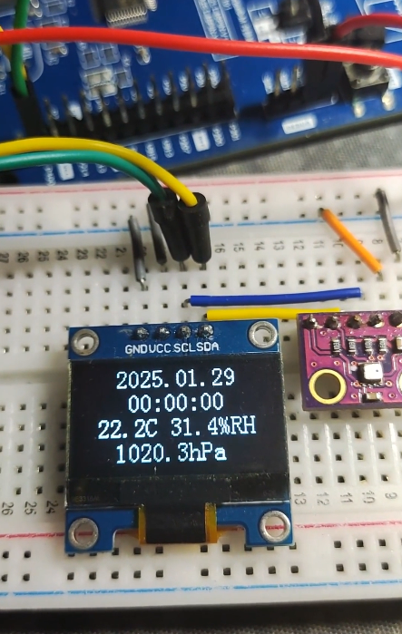
把编译好的程序下载到开发板并复位。观察到 OLED 屏幕上正确显示了预设的时间和获取到的温湿度气压值。
可以打开串口助手,在发送框输入 time:20250128235958。
总结与思考
本实验通过瑞萨 FSP 图形化配置工具,快速完成了 I²C 主控制器、引脚和通讯参数的设置,大大降低了底层驱动开发的复杂度。随后,我们成功移植了 SSD1306 OLED 驱动和 BME280 传感器驱动,并结合 RTC 功能,实现了一个简单的环境监测显示终端。
过程中有几个关键点需要注意:
- 地址转换:注意常见 OLED 驱动代码中的 8 位地址(含读写位)与 FSP 中配置的 7 位地址之间的转换。
- 开漏输出:I²C 引脚需要配置为开漏输出模式。
- 通信延时:与 BME280 等传感器通信时,在写入命令后需添加适当延时,等待传感器准备好数据。
- 显示优化:使用显存(
OLED_GRAM)缓存再一次性刷新,可以极大提高 OLED 的显示刷新效率,避免字符“蹦”出来的现象。
这个项目展示了如何利用瑞萨 RA MCU 和 FSP 生态,高效地集成多种外设(I²C、RTC、传感器、显示)来完成一个实际应用。如果你在驱动移植、I²C 地址配置或传感器数据补偿算法上遇到问题,欢迎在技术社区交流探讨,例如在 云栈社区 与更多嵌入式开发者一起分享和解决。
 发表于 2026-4-19 06:24:57
|
查看: 183|
回复: 0
发表于 2026-4-19 06:24:57
|
查看: 183|
回复: 0
